

A filter capacitor in a power supply circuit is chosen according to circuit stress. It is not selected from microfarads alone. Start with load current. Next, consider ripple frequency. Also include allowable ripple voltage. Then check voltage margin. Review ESR. Check ripple current. Look at ESL. Consider temperature. Examine lifetime. Review frequency response. The waveform decides the final choice.
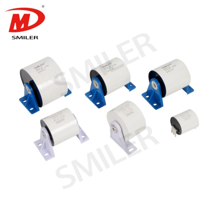
After a rectifier, voltage rises near each input peak. It falls before the next peak. A capacitor charges to a high level. It then discharges into the load as voltage drops. This process reduces bus or output ripple.
That is why a capacitor is used after a rectifier. It supplies stored energy between recharge pulses. This action gives the load a smoother voltage.
Low-frequency ripple filtering is mostly bulk energy storage. In a full-wave 50/60 Hz rectifier, the capacitor supports the load between charging peaks. High-frequency noise filtering is different. Switching edges become important. Loop inductance matters. ESR and ESL play a role. Self-resonance dominates in this case.
A larger uF value is not automatically better at every frequency. A big bulk capacitor may smooth low-frequency ripple. It can still have too much impedance for fast switching noise.
For a simple first estimate, use this formula.
C ~= I / (f x Delta V)
C is the required capacitance. I is load current. F is ripple or recharge frequency. Delta V is the allowable ripple voltage. A 1 A load with 1 V ripple at 100 Hz starts near 0.01 F. This equals 10,000 uF.
Topology can change the final value. Conduction angle affects it. Hold-up time matters. Load steps influence the result. Current waveform can move the value as well.
A 50/60 Hz rectified supply generally needs more bulk capacitance. The recharge pulses are far apart. In a switching power supply, energy may be processed at tens of kilohertz or higher. Capacitance can be smaller in this case. Sharper ripple-current waveforms become important. High-frequency impedance matters more too.
The same capacitance value can behave well in one topology. It can perform poorly in another. Frequency changes the math. It affects heating. It increases layout sensitivity.
The formula treats the capacitor as ideal. Real parts have ESR. They also have ESL. Tolerance exists. Aging occurs. Temperature drift is present. Ripple-current limits apply. Voltage derating must be considered. Mounting limits exist.
SMILER capacitor selection guidance for high-stress power circuits keeps the calculated value conditional. It depends on dV/dt. Peak current is reviewed. RMS current is checked. Temperature rise matters. Loop length is important. Final waveform validation occurs before the BOM is locked. The uF value starts the selection. Electrical and thermal checks finish it.
Choose a voltage rating from the highest stress the capacitor will see. This includes continuous bus voltage. It covers startup overshoot. Line variation is considered. Switching spikes matter. Load dump is reviewed. Fault or transient conditions are included. One fixed margin does not fit every supply.
The part must meet the real maximum operating voltage. This applies under the datasheet conditions for temperature. Humidity is reviewed. Insulation is checked. Test voltage matters. Lifetime is considered.
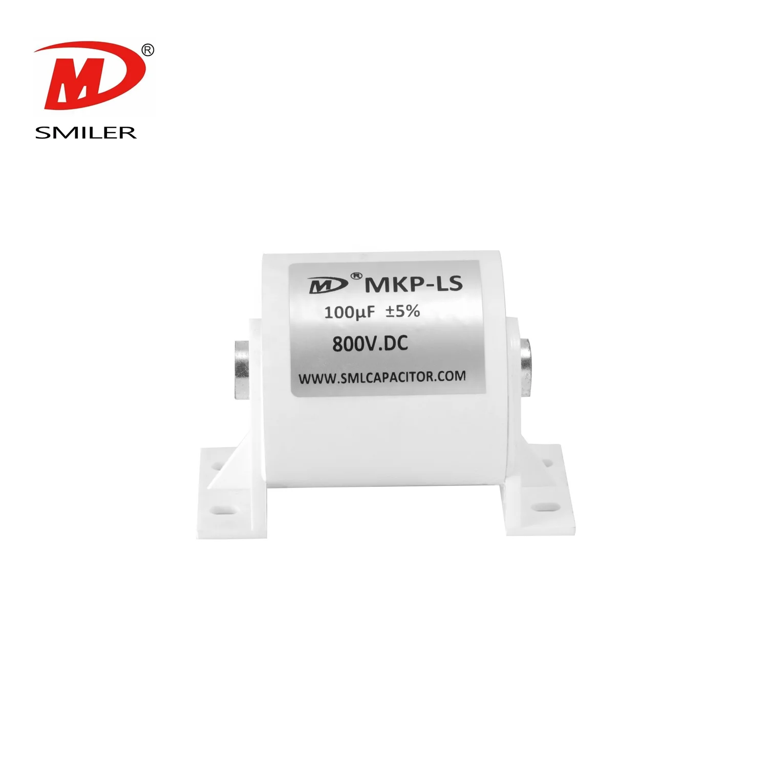
For SMILER capacitor MKP-LS DC-filter parts, published data include a 500-1400 VDC range. They cover a 1-200 uF capacitance range. They reference IEC 61071 and GB/T 17702. They include 1.5 times rated-voltage terminal testing for 10 seconds. Terminal-to-case testing is listed. Biased-humidity testing appears. Lifetime at rated voltage and 85 C is provided.
ESR adds ripple voltage. It turns ripple current into heat. Excessive temperature shortens capacitor life. A part can have enough capacitance. It can still fail if its RMS ripple-current rating is too low.
The DC-Filter Capacitor MKP-LS is published with low equivalent series resistance. It offers low self-inductance. It provides good heat dissipation. It has current-impact capability for AC/DC filtering and high-frequency, high-current conditions.
ESL limits response to fast current changes. Above self-resonance, the part can look more inductive than capacitive. Low-inductance construction helps. Short loops matter around rectifiers. They are important near switches. They matter in DC-link paths.
Large bulk capacitors often work best with smaller high-frequency capacitors near the noise source. Increasing uF rarely fixes poor high-frequency behavior. It does not correct layout problems.
There is no single best type. Electrolytic capacitors offer high capacitance density for bulk energy storage. Film capacitors are useful where low ESR matters. They help with ripple-current capability. They provide stability. They handle pulse stress. They support long service life. Ceramic capacitors are strong for high-frequency bypassing. Actual capacitance can shift with dielectric type. It changes with DC bias. Voltage affects it. Temperature influences the value.
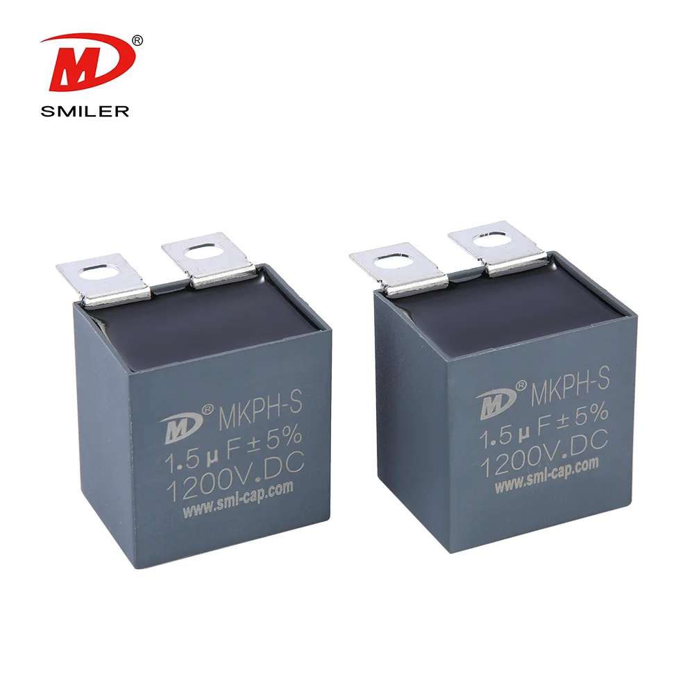
For switch-mode power supplies and IGBT buffer circuits, the SMILER capacitor MKPH-S uses metallized polypropylene film. It has a plastic shell package. It includes UL94 V-0 resin filling. It offers high pulse intensity. It provides self-healing behavior. It delivers high reliability and long useful life.
Use more than one value when the supply has both slow energy-storage demand and fast switching-noise demand. A bulk capacitor supports the bus. A smaller bypass capacitor reduces local high-frequency impedance.
Check values against impedance. Review technologies and placement. Consider ripple-current sharing. Examine control-loop behavior. One larger capacitor may not cover the range.
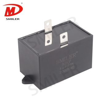
A film capacitor makes sense when the design needs high ripple current. It fits when low ESR is required. Low inductance helps. High-frequency operation is supported. DC-link filtering benefits. AC output filtering improves. Elevated temperature is managed. Long lifetime is achieved.
SMILER capacitor uses metallized polypropylene film in relevant power capacitor families. Our portfolio includes DC-Filter/DC-Link parts and AC Filter Capacitor MKP-AM products for applications such as power converters, UPS equipment, motor drives, and high-current filtering.
Do not verify only at nominal load. Check maximum load. Review input-voltage extremes. Examine frequency limits. Consider ambient temperature. Look at startup. Study transients. Include realistic cooling.
Measure ripple voltage. Check RMS ripple current. Review case temperature. Examine hotspot risk. Filter design also has to consider harmonic performance. It includes steady and transient component duty. Resonance is reviewed. Protection matters. Reliability is important. Equipment ratings must be checked.
Do not compare only nameplate uF and voltage. Check capacitance tolerance. Review ESR at frequency. Look at allowable RMS current. Examine temperature derating. Consider dV/dt. Check insulation. Review humidity testing. Study lifetime.
For example, SMILER capacitor product data include ratings such as capacitance range and voltage range. They list climatic category. They show voltage derating above the stated temperature. They provide terminal test voltage. They include humidity testing. They tie lifetime to operating conditions. Read datasheet values with their test conditions. Do not treat them as isolated numbers.
Common mistakes include choosing only by capacitance. They involve ignoring ripple-current rating. They include leaving too little voltage margin. They cover checking ESR at the wrong frequency. They involve overlooking temperature derating. They include assuming one large capacitor filters every frequency. They involve ignoring size, mounting, inductance, and airflow.
A safer workflow is to calculate the starting capacitance. Then choose the type for frequency and current stress. Confirm voltage and temperature limits next. Finally, verify the waveform. For product comparison, use the power capacitor product range with the design conditions.
A: Start with C ~= I / (f x Delta V). I is load current. F is the ripple or recharge frequency. Delta V is the allowable ripple voltage. Then check ripple current. Review ESR. Examine temperature. Look at voltage stress. Consider transients.
A: It depends on load current. It relies on ripple frequency. It includes allowable ripple voltage. Topology affects the choice. Hold-up needs matter. Transients influence the value. A 50/60 Hz rectified supply often needs more bulk capacitance. Ripple-current and thermal limits still matter.
A: ESR adds to the ripple voltage. It turns ripple current into heat. Too much heat speeds aging. It can cause early failure. This happens even when capacitance and voltage rating look acceptable.
A: Use electrolytic capacitors for high bulk capacitance. Choose film capacitors for ripple current. They work well for low ESR. They handle pulse stress. They provide stability. They support service life. Use ceramic capacitors for local high-frequency bypassing.
A: Choose a rating above the real continuous voltage. Include startup stress. Consider transient and fault voltage stresses. Apply derating based on the datasheet temperature. Review lifetime conditions. Avoid a fixed margin
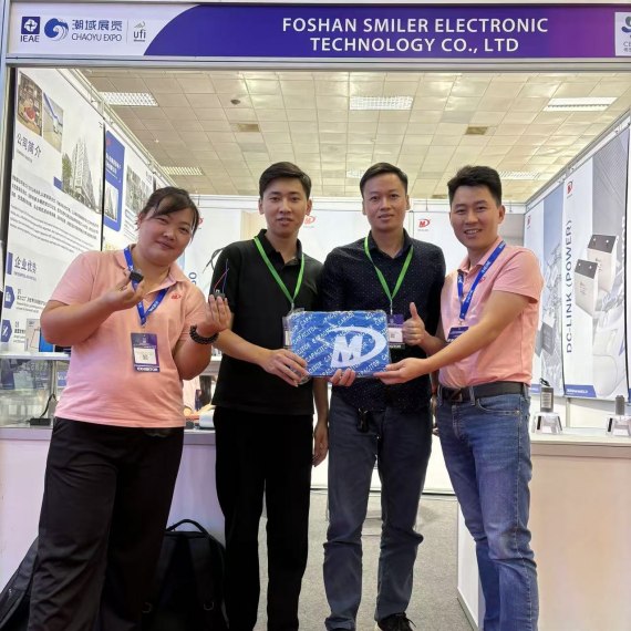
2024 VIETNAM INTERNATIONAL ELECTRONICS & SMART APPLIANCES EXPO
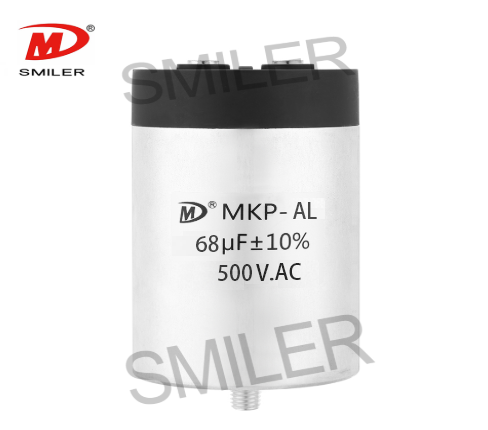
Exploring How AC Capacitors and DC Capacitors Function Differently
Understanding Snubber Capacitor: RC vs. RCD Snubber Differences
What Drives AC Capacitor Cost? A Comparison with DC Capacitors
Snubbing Capacitors in Power Electronics: RC vs. RCD Snubber


 Add
Building 12,Huazhi Technology Innovation Center,28 Sanle East Road,Beijiao,Foshan,Guangdong,China
Add
Building 12,Huazhi Technology Innovation Center,28 Sanle East Road,Beijiao,Foshan,Guangdong,China
 Phone
+86 18007576965 / 0757-22391591
Phone
+86 18007576965 / 0757-22391591
 Email
ari@sml-cap.cn
Email
ari@sml-cap.cn



