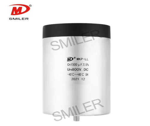
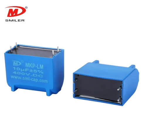
Capacitors play a role in electronics by storing and releasing electrical energy in an efficient way using two conductive plates with an insulating material in between referred to as the dielectric layer. When a voltage is applied between the plates a capacitor can store energy. Then release it as required. This ability makes capacitors indispensable for tasks, like filtering signals storing energy and providing buffering in circuits.
Direct Current (DC) is defined as the unidirectional flow of electric charge, delivering stable voltage and current to systems requiring consistent power. Key features include:
Safety & Voltage Regulation:
DC systems, such as 24V configurations, prioritize safety in low-voltage applications. By operating at reduced system voltages, current levels are minimized, lowering risks like overheating or electrical hazards.
Comparison with AC:
While AC coils may achieve higher initial power due to inrush current characteristics, DC systems excel in applications demanding steady energy flow and simplified circuit architecture.
Applications:
DC is widely used in power supply units, control circuits, and devices requiring stable voltage (e.g., automotive electronics and industrial systems). Its predictable behavior enhances circuit functionality and component integration.
SMILER is a leading player in capacitor technology advancements by providing cutting-edge solutions tailored for enhancing performance in DC environments. Its established automated production facilities guarantee effectiveness and accuracy while maintaining a high level of consistency. They can produce up to 300k units with a remarkable success rate exceeding 99.93%. SMILER’s DC link capacitors have been designed to substitute electrolytic capacitors with enhanced attributes, like reduced Equivalent Series Resistance (ESR) effective handling of ripple current flow self-repairing capabilities and extended longevity.
When you connect a capacitor to a DC power source the current starts moving into the capacitor plates. This flow persists until the capacitor voltage matches that of the power source. As this happens electrons build up on one plate while they are taken away from the plate resulting in an electric field that stores energy in the dielectric material. Capacitors inherently block steady DC current but allow transient currents during charging and discharging. This contrasts with AC systems, where continuous current flows due to periodic voltage reversal.
When a capacitor is charged with DC it undergoes important internal processes. Firstly the voltage, across the capacitor rises quickly as it starts to store energy. As more charge builds up on the plates the voltage increase rate slows down until it matches the applied voltage. This stage indicates charging when no additional current enters the capacitor since it has reached its maximum storage limit.
 SMILER utilizes cutting-edge technologies to enhance capacitor charging efficiency. Their capacitors feature:
Low ESR and high ripple current tolerance
Minimal inductance (Ls) and self-healing properties
Extended lifespan under demanding conditions (e.g., DC Link MKP-LL applications)
The self-healing mechanism automatically recovers from dielectric breakdown events, significantly prolonging operational durability.
 The size of a capacitor plays a role in how fast it can get charged up. The capacitance is measured in farads and it shows how much electric charge a capacitor can hold. A bigger capacitance allows the capacitor to store more charge but it also means it will take longer to fully charge when connected to a DC power source. This happens because the increased capacity requires more time for electrons to build up on the plates until the voltage matches that of the power source.
SMILER’s DC-Link Capacitors are engineered with varying capacitance ranges to cater to different application needs. With capacitance values ranging from 24μF to 5600μF, these capacitors offer flexibility in choosing the right component for specific charging time requirements. The DC Link MKP-LM provides large capacitance in compact sizes, ensuring efficient energy storage and quick charging capabilities.
The strength of voltage greatly decides the speed at which a capacitor is charged to capacity. The speed at which a capacitor receives its charge is greater with higher levels of voltage being applied. However, one should be careful not to surpass the voltage limit of the capacitor to prevent any breakdown or damage.
SMILER’s capacitors are made to have a range of voltages starting from 600 volts to 4000 volts for their DC link Capacitors and up to 1200 volts for their MKP LM models. This broad voltage capacity gives users the flexibility of choosing capacitors that match their specific voltage needs while having the assurance of quality performance.
Leveraging the understanding of varying applications having distinct needs, SMILER provides solutions that are customized to suit various uses ranging of industry needs. Whether it means altering capacitance values or optimizing voltage ratings, SMILER offers solutions that guarantee seamless integration with numerous electronic systems.
They use production techniques to engineer capacitors that precisely match the demands for high-class performance across a broad spectrum of applications from renewable energy systems like solar power and wind power inverters to transportation technologies such as electric vehicles and hybrid electric vehicles. SMILER’s capacitors exhibit flexibility and adaptability in use.
A: SMILER utilizes important methods to guarantee the durability and dependability of their capacitors. By integrating attributes such as self-repair capabilities and strong resistance to humidity in their designs. SMILER’s capacitors are made to remain unaffected by tough environmental conditions without compromising their best working. Polypropylene film dielectric medium adds longevity, while aluminum shell package or plastic shell package (PPS) offers protective strength against external influences. In addition, SMILER’s strict test procedures involve subjecting their capacitors to humidity tests for periods of up to 1000 hours at 60°C with 95% relative humidity to confirm that the capacitors are in the same performance level, for prolonged periods.
A: SMILER’s DC-Link capacitors feature ultra-low stray inductance (ESL≤5nH) and high pulse current tolerance (up to 30kA) to protect SiC modules from voltage spikes in high-frequency switching applications. The polypropylene film structure has stable performance up to 2000VDC with self-healing properties to ensure reliability under extreme conditions. SMILER’s capacitors are easy to fit into 1200V/1700V SiC inverter systems, reducing voltage overshoot and enhancing thermal management.
A: As opposed to electrolytic capacitors, SMILER’s film DC-Link capacitors eliminate voltage balancing problems in series applications (common in 600V+ systems) and offer:
Longer Lifespan: No evaporation of electrolytes enables consistent performance for over 100,000 hours of operation.
High-Temperature Robustness: Tested for +105°C ambient operating conditions, with solar/wind inverter and electric vehicle traction application.
Ultra-Low ESR: <0.5mΩ reduces heat losses, beating electrolytes in high-ripple applications like variable-frequency drives.
Their UL94 V-0 flame-retardant encapsulation enhances safety in critical applications.