

A capacitor input filter circuit plays a key role in many power supplies. A rectifier turns AC into current that flows in one direction. Yet that output still rises and falls with every rectified peak. The capacitor input filter stores energy near the peaks. It releases the energy between those peaks. This helps downstream circuits receive smoother DC. They no longer receive raw pulsating DC.
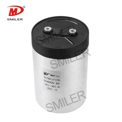
In a basic path from AC to DC, the sequence is clear. It starts with the AC input. Then comes the rectifier. Next is the capacitor input filter. After that comes the regulator or load. The filter capacitor connects across the rectifier output. It sits in parallel with the load. This makes it the first energy storage part the rectified voltage meets. This setup differs from a general signal filter. It also differs from a small input bypass capacitor placed beside an IC.
When rectifier voltage rises, the capacitor charges near the peak. When the rectifier voltage falls below the capacitor voltage, the capacitor supplies current to the load. It recharges at the next rectified peak. The output is not perfectly flat. Yet the valleys become shallower.
In rectifier power supplies, the terms capacitor filter, smoothing capacitor, and reservoir capacitor often describe the same practical function. The phrase capacitor input filter circuit is more specific. It indicates that the first filter element after the rectifier is a shunt capacitor. It is not an inductor. It is not a multi-stage network.
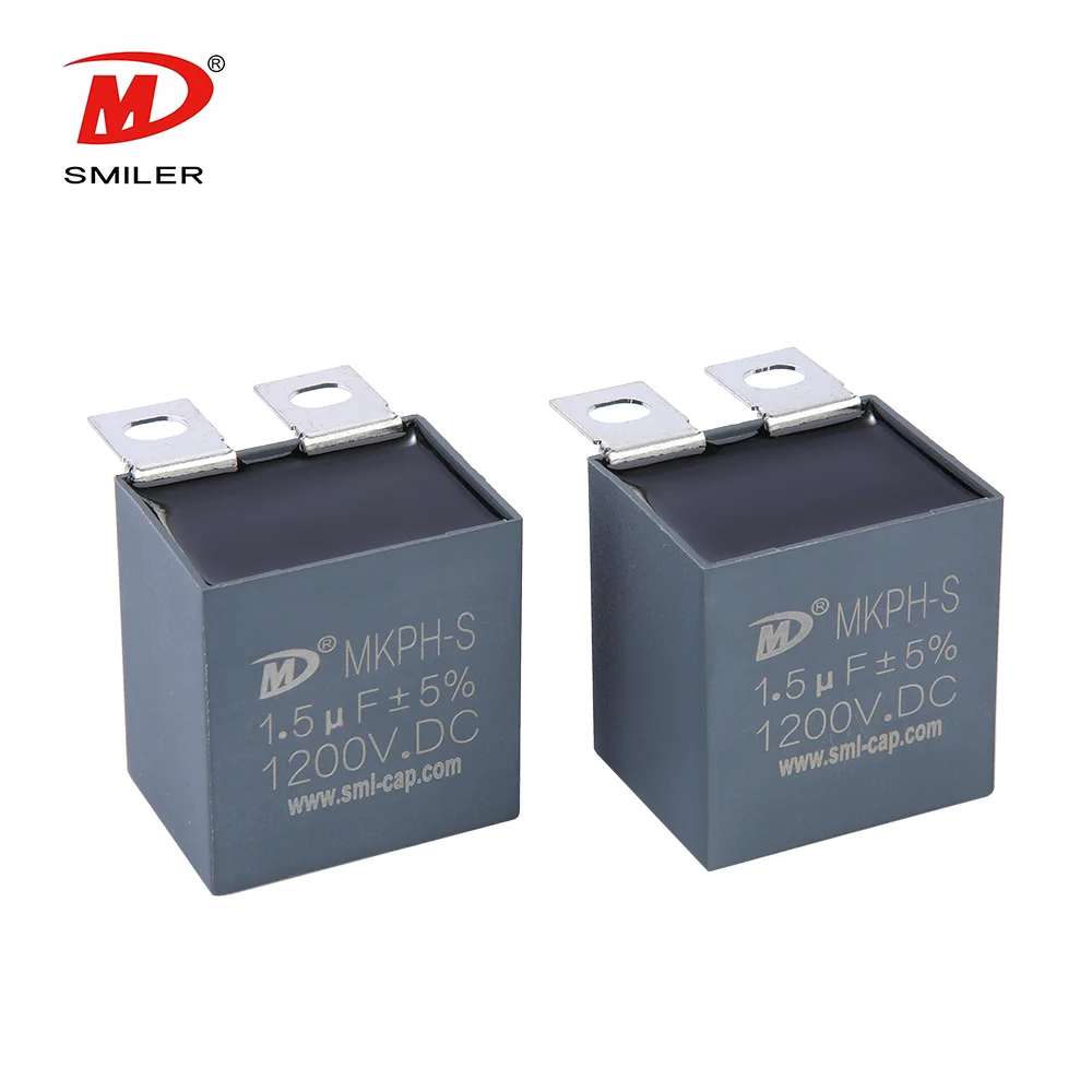
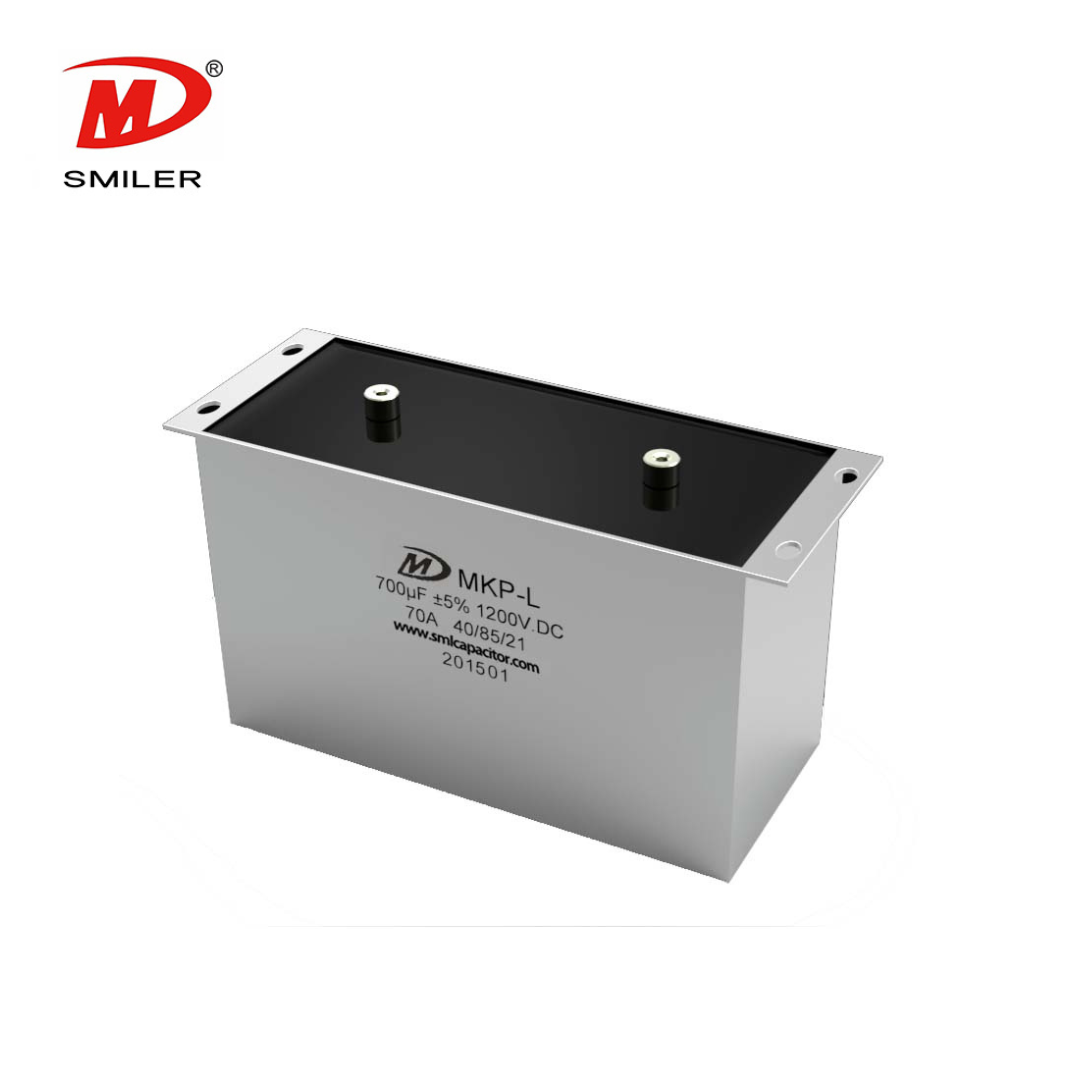
Ripple matters in these systems. Control circuits, logic rails, analog front ends, drivers, and communication interfaces expect a DC supply inside a defined operating window. A capacitor input filter reduces the voltage swing before later regulation. In larger conversion stages, SMILER capacitor DC-filter and DC-link designs use metallized polypropylene film. They provide low equivalent series resistance. They offer low self-inductance. They support good heat dissipation and current-impact capability. These features help AC/DC filtering under high-frequency, high-current conditions.
This circuit appears in linear supplies. It is used in unregulated DC outputs. It serves chargers and adapters. It supports industrial control power rectifier front ends and DC bus stages. The exact capacitor type changes with voltage, current, frequency, package lifetime, and safety requirements. SMILER capacitor also publishes AC filter capacitor structures based on metallized polypropylene film. These use a plastic shell package and UL94 V-0 resin filling for output AC filtering in power converters, UPS, and motor drives. In practical AC to DC filter circuit design,the capacitor family still has to match real electrical and thermal stress.
A capacitor input filter usually does not create the final precision rail by itself. The common design logic begins with the rectifier. It continues with bulk smoothing. Then comes remaining ripple filtering and regulation. Cleaner DC before the regulator reduces dropout pressure. It lowers heat and noise sensitivity. Sensitive loads may still need RC, LC, common-mode, or active regulation stages.
In a half-wave rectifier, the capacitor is recharged once per line cycle. In a full-wave rectifier, it is recharged twice per line cycle. This makes the discharge interval shorter. With the same load current and capacitance, the full-wave circuit usually produces lower ripple.
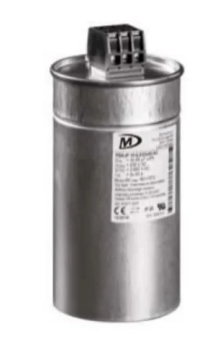
Ripple grows when load current rises. The capacitor loses more charge between peaks in that case. Ripple falls when capacitance increases. Voltage drops more slowly for the same current. Ripple also falls when recharge frequency rises. This explains why a filter that looks acceptable at no load can show much larger ripple at full load.
Discharge behavior is tied to load resistance and capacitance. A useful shorthand is tau equals R times C. A longer time constant lets the output stay closer to the previous peak. A heavier load lowers effective resistance. This shortens discharge time and increases ripple.
A common first estimate is C equals I divided by f_ripple times delta V. Here, C is capacitance. I is load current. F_ripple is the recharge frequency. Delta V is acceptable peak-to-peak ripple. The result is only a starting point. Transformer impedance, diode conduction angle, ESR, regulator dropout, heat, and waveform shape can change the final value.
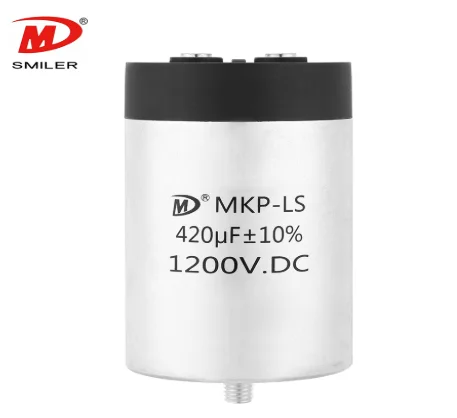
Capacitance is only one line in the selection checklist. Designers also need rated voltage, ripple current, ESR, operating temperature, thermal rise, frequency conditions, expected lifetime, insulation, and mounting. SMILER capacitor has over 15 years of expertise in film capacitors, with customization availability, low MOQ, and automated production lines designed for efficiency, precision, consistency, and quality control. Our film capacitor selection process treats those limits as inputs. For DC filtering and DC-link use the Power Capacitor DC Link Capacitor MKP-LS publishes 500-1400 VDC and 1-200 uF ranges IEC 61071 and GB/T 17702 references 1.5 x rated-voltage terminal testing for 10 seconds 3000 VAC terminal-to-case testing 50000 hours at rated voltage and 85 C and a 1000 hour biased-humidity test at 60 C and 95% RH with rated voltage.
A larger capacitor can reduce ripple. Yet it also shortens the charging interval and raises peak charging current. That can increase rectifier diode stress, transformer current, startup inrush, capacitor ripple-current demand, and heat. A better target is the smallest robust value that meets ripple transient, thermal lifetime, and cost requirements.
A single capacitor input filter is attractive for simple smoothing after a rectifier. RC filtering can add attenuation where current is modest, and voltage drop is acceptable. LC and pi filters are stronger choices when ripple noise or current stress cannot be controlled by bulk capacitance alone. The power capacitor product category shows how different capacitor families serve different filtering and conversion roles.
Additional filtering becomes important when load current is high. It is needed when ripple limits are strict. It matters when analog or control circuits are sensitive. It applies when switching noise is present or rectifier peak current is excessive. In HVDC engineering, filtering may be combined with smoothing reactors, converter design controls, route measures, and changes to affected communication systems. Resonance, transient duty, protection reliability, noise location, and parallel operation can influence the final architecture.
Verification closes the design loop. Measure no-load and full-load voltage. Check peak-to-peak ripple. Examine capacitor temperature, rectifier peak current, startup behavior, and input-voltage extremes. For high-power DC filtering, teams may also assess harmonic-current duty, transient rating, cooling, insulation coordination, protection, and criteria such as induced voltage or equivalent disturbing current.
A: It is a rectifier-output filter where a capacitor is connected across the load as the first smoothing element. The capacitor charges near rectified voltage peaks. It discharges between peaks. This reduces the ripple in pulsating DC.
A: Use C equals I divided by f_ripple times delta V as a first estimate. Then check the real waveform shape, diode current, transformer or source impedance, regulator margin, ESR, temperature rise, ripple current, and lifetime.
A: Rearranging the same first-order estimate gives delta V equals I divided by f_ripple times C. It is useful for early sizing. Yet measured ripple under real load is still the design authority.
A: The advantages are simplicity, low cost, compact layout, and strong smoothing for many rectifier supplies. The disadvantages are ripple under heavy load, high peak charging current, inrush stress, thermal demand, and the need for additional filtering or regulation in tighter designs.
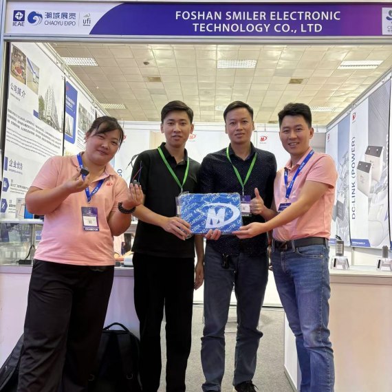
2024 VIETNAM INTERNATIONAL ELECTRONICS & SMART APPLIANCES EXPO
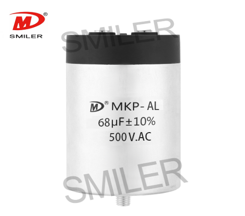
Exploring How AC Capacitors and DC Capacitors Function Differently
Understanding Snubber Capacitor: RC vs. RCD Snubber Differences
Understanding DC Capacitance to Prevent Converter Oscillations
Mastering AC to DC Rectifier with Capacitor Techniques


 Add
Building 12,Huazhi Technology Innovation Center,28 Sanle East Road,Beijiao,Foshan,Guangdong,China
Add
Building 12,Huazhi Technology Innovation Center,28 Sanle East Road,Beijiao,Foshan,Guangdong,China
 Phone
+86 18007576965 / 0757-22391591
Phone
+86 18007576965 / 0757-22391591
 Email
ari@sml-cap.cn
Email
ari@sml-cap.cn



