

A VFD appears neat on a block diagram. Yet the DC bus remains an active area. Line rectification, inverter switching, motor torque changes, and cabinet temperature all come together at the capacitor bank. For a high-ripple drive, the DC-Link Capacitor should not be chosen by microfarads alone. It must keep the bus stable. It needs to carry ripple current. It has to release heat. And it must still reach the expected service life.
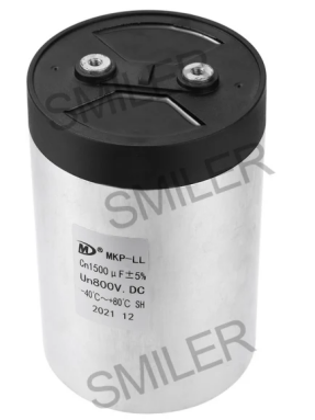
The rectifier fills the DC bus. The inverter then chops that bus into a controlled motor output. The DC-Link Capacitor sits between them. It works as a short-term energy buffer. It also acts as a local current source. This occurs when motor demand changes faster than the input stage can respond. It gives high-frequency ripple current a shorter path than the upstream supply. In medium- and high-voltage VFD applications, the MKP-LL Series DC Link Capacitor is used for DC filtering and smoothing.
Ripple current in a VFD rarely stays at one clean frequency. The rectifier pulls current in pulses. The inverter returns switching-frequency components. The motor load may swing during acceleration, deceleration, pumping, hoisting, or braking. A light-duty estimate can miss those overlaps. When ripple current rises, the capacitor warms internally. That heating is why the RMS ripple-current rating and the cabinet cooling path often decide the design.
DC bus ripple is the voltage movement left after the capacitor supplies and absorbs current. Too much ripple can appear as a torque disturbance. It can cause nuisance trips or unstable control behavior. It may add extra stress on inverter devices. More capacitance reduces low-frequency voltage swing. Yet it cannot rescue poor thermal margin. Start with the largest bus ripple the drive can tolerate at the worst line, load, and braking condition.
For a first pass, use C ~= I / (f_ripple x delta V). Here, I is the ripple-producing current component. f_ripple is the dominant ripple frequency. Delta V is the allowed peak-to-peak bus ripple. The inputs still need judgment. These include DC bus voltage, load power, rectifier type, switching frequency, motor duty profile, regeneration behavior, and cooling space. For broader inverter context, the discussion of DC link capacitor design for 3 phase inverter efficiency is useful. The final value should come from the actual VFD duty cycle and verification test.
A capacitor can have the calculated capacitance and still be the wrong part. Ripple current flows through ESR. The I squared R loss becomes heat inside the winding or film structure. The rating also depends on frequency and cooling. One catalog reference condition is not enough. In a high-ripple VFD, start with measured or simulated RMS ripple current. Then check capacitance, voltage, and lifetime together.
ESR is the loss term engineers usually feel first. Lower ESR means less heat at the same ripple current. ESL matters when inverter edges are fast. Extra inductance makes the capacitor slower to accept high-frequency current. It can leave sharper bus spikes. Layout still matters. Yet it cannot fully compensate for the wrong high-frequency behavior. SMILER capacitor DC-filter and DC-link designs use metallized polypropylene film. They offer low equivalent series resistance, low self-inductance, heat dissipation, and current-impact capability for AC/DC filtering and high-frequency, high-current conditions.
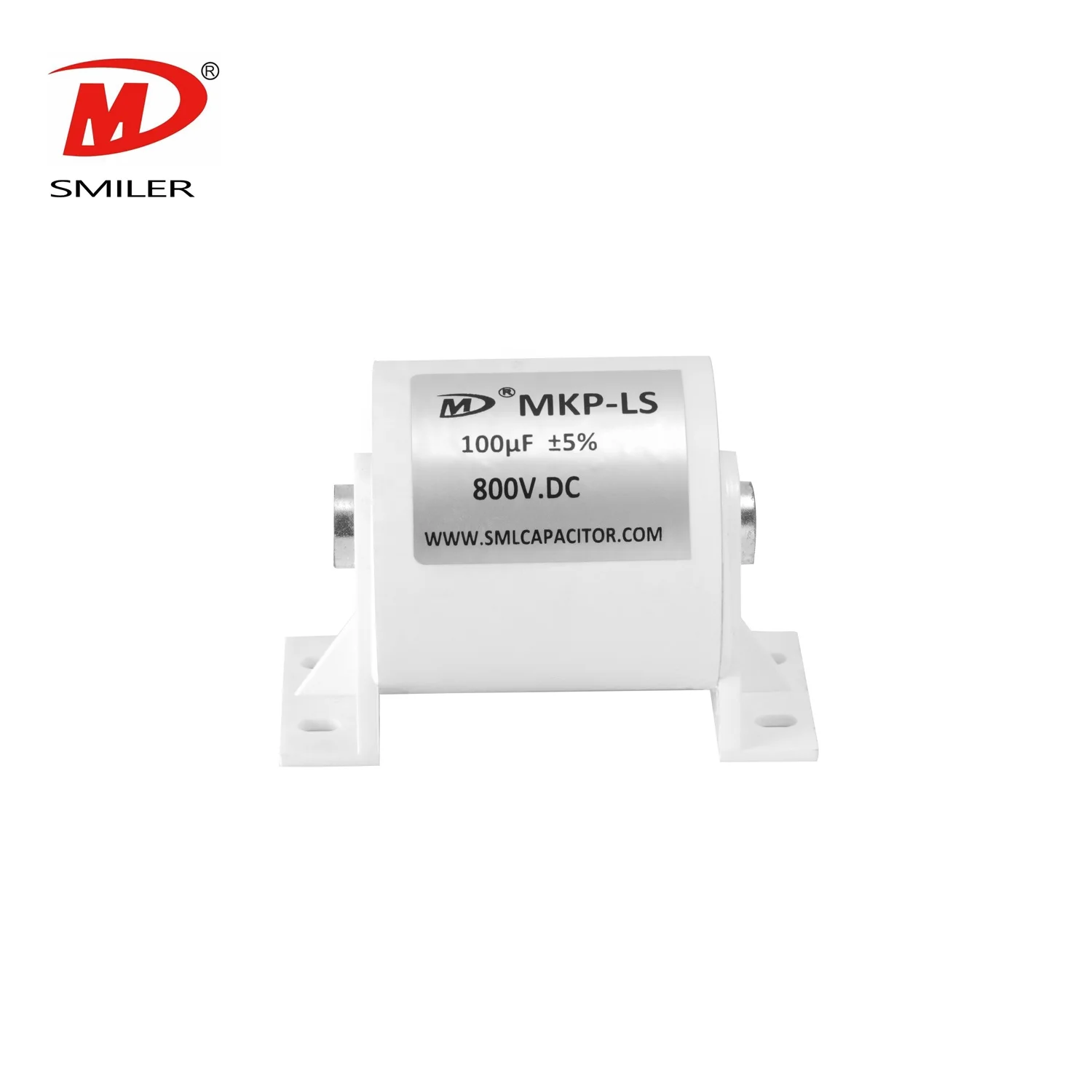
Temperature is one of the strongest lifetime variables. Ripple current heats the winding or film structure. Ambient heat inside a drive cabinet raises the baseline temperature further. Published MKP-LS data includes 50000 hours at rated voltage and 85 C. It also shows a 1000-hour biased-humidity test at 60 C and 95% RH with rated voltage. Those figures are useful reference points. Each VFD still needs thermal validation at its own airflow, mounting, and current profile.
Voltage rating should cover the normal DC bus, line tolerance, braking events, and switching transients. Ripple current rating should cover RMS current at operating temperature. It needs margin for aging and airflow variation. For VFD DC filtering and smoothing, the MKP-LL Series DC Link Capacitor range extends from 10 uF to 5000 uF and from 600 VDC to 7000 VDC. That range supports broad design coverage. Final selection still depends on the calculated stress profile. The Power capacitor DC link capacitor MKP-LL page is the relevant product reference for this VFD DC-link role.
Film DC-Link Capacitors are common where maintenance access is costly or ripple current is severe. Metallized polypropylene film generally gives lower loss. It provides better high-frequency behavior and self-healing behavior compared with many electrolytic banks. In related motor-drive output filtering, the MKP-AM film capacitor uses metallized polypropylene film, a plastic shell, and UL94 V-0 resin filling. Published features include large capacitance, small size, over-voltage and over-current capability, high reliability, self-healing property, and long lifetime. SMILER capacitor also provides film-capacitor expertise. It offers customization availability with low MOQ and automated production lines designed for efficiency, precision, consistency, and quality control. Our selection process treats ripple current and temperature as design inputs. They are not afterthoughts.
Electrolytic capacitors still appear where budget is tight, or the required capacitance is very large. They can work when ripple current is moderate. Maintenance expectations must be clear and replacement acceptable. The trade-off is familiar. It includes higher ESR, stronger temperature sensitivity, polarity limits, and shorter life at elevated heat. When the drive must run for years in a hot cabinet, a film solution may reduce service risk. This holds even if the first component price is higher. Engineers comparing product families can use the DC-Link Capacitor product category as a starting point.
Ripple current turns into heat. Heat accelerates aging. Over time, capacitance can drift down. Losses can rise. Terminations or mounting points can see more stress from thermal cycling. The real cause is often a stack-up. It includes underestimated ripple current, high ambient temperature, weak airflow, long current loops, and not enough margin.
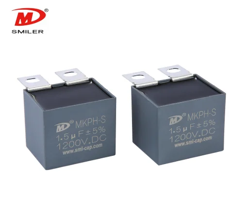
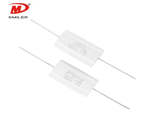
Use ripple-current margin. Keep the capacitor away from hot components. Provide airflow. Minimize high-current loop inductance. Verify mounting against vibration. Test no-load, rated-load, overload, acceleration, deceleration, and braking conditions. Snubber capacitors have a different job. MKPH-S is used for snubber and IGBT protection in VFD systems. The DC-Link Capacitor handles bus filtering and smoothing.
Follow the workflow in order. Define the DC bus voltage, line tolerance, load power, and motor duty. Calculate capacitance for the allowed ripple voltage. Evaluate RMS ripple current and frequency spectrum. Check temperature rise and lifetime at real cabinet airflow. Finally, verify mounting, insulation, safety margin, and production test conditions before locking the BOM.
A: It buffers energy between the rectifier and inverter stages. It stabilizes DC bus voltage. It provides a low-impedance path for ripple currents created by rectification and inverter switching.
A: It should exceed the expected RMS ripple current at the actual temperature and frequency spectrum. It needs a design margin for load changes, braking events, airflow variation, and aging.
A: High ripple current creates internal heating through ESR. That heat accelerates aging. It reduces capacitance. It stresses terminations. It shortens service life if cooling and current margin are insufficient.
A: Lifetime depends on voltage stress, ripple current, temperature, humidity, airflow, and mounting. Published life data can guide screening. Each industrial VFD design should be verified under its own operating profile.
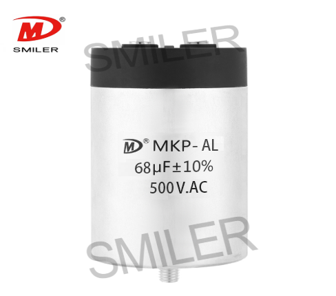
Exploring How AC Capacitors and DC Capacitors Function Differently
RC vs. RCD Snubber: Key Differences and Applications Explained
What Drives AC Capacitor Cost? A Comparison with DC Capacitors
Snubbing Capacitors in Power Electronics: RC vs. RCD Snubber
Understanding How DC Current in Capacitor Initiates Charging


 Add
Building 12,Huazhi Technology Innovation Center,28 Sanle East Road,Beijiao,Foshan,Guangdong,China
Add
Building 12,Huazhi Technology Innovation Center,28 Sanle East Road,Beijiao,Foshan,Guangdong,China
 Phone
+86 18007576965 / 0757-22391591
Phone
+86 18007576965 / 0757-22391591
 Email
ari@sml-cap.cn
Email
ari@sml-cap.cn



